

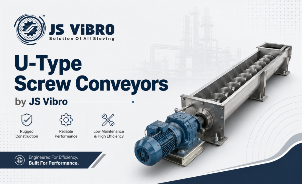
The U-Type Screw Conveyor (often called a U-trough screw conveyor) is a cornerstone of modern bulk material handling. It is designed to transport powders, granules, flakes, and semi-solid matrices horizontally or at shallow inclines. Structurally, it consists of a rotating helical screw blade known as flighting welded onto a central pipe shaft. This entire assembly rotates inside a stationary, open-top U-shaped channel.Unlike enclosed pipe (tubular) conveyors, the U-trough design uses a removable flat cover plate.
Component Anatomy & Structural Design
- Trough and Cover Assemblies: The U-shaped trough forms the primary structural body. Fabricated from sheet metal or plate steel, its radius closely matches the outer diameter of the screw. The top is sealed with a modular cover plate secured by bolts or quick-release toggle clamps. Dust-tight operation is achieved by placing specialized gaskets (such as neoprene, silicone, or EPDM) between the trough flange and the cover.
- The Screw (Flighting & Pipe Shaft): The helical flighting is formed from steel strips and continuously welded to a heavy-wall center pipe. The pipe must withstand torsional forces from the motor and resist bending forces caused by gravity and material weight.
- Trough Ends and Seals: Solid end-plates close off the terminal ends of the U-trough. These plates support the main thrust bearings that hold the screw shaft. To prevent material from leaking into the bearings, designers use mechanical shaft seals, packing glands, or air-purged seals.
- Drive Unit Configuration: The drive mechanism consists of an electric motor coupled to a speed reducer (gearbox). This assembly provides the high torque and low rotational speeds needed to push heavy bulk materials. The drive can be directly coupled to the shaft, foot-mounted with a flexible coupling, or top-mounted using a V-belt and sprocket mechanism.
Shafted vs. Shaftless Systems
When engineering a U-type conveyor, selecting between a traditional shafted design and a modern shaftless configuration is a critical decision.
Shafted Screw Conveyors
- Advantages: Outstanding structural rigidity over long spans. It allows for precise control of the gap between the flight and the trough wall.
- Limitations: The center pipe takes up physical space inside the trough, reducing the total volume available for material. Additionally, sticky or cohesive products can wrap around the central shaft, causing material buildup and blockages.
- Advantages: The absence of a center shaft creates a completely open material path. This is ideal for handling difficult materials like municipal wastewater sludge, stringy biomass, tangled wood chips, or wet adhesive waste.
- Limitations: Because the spiral rests on the bottom of the trough, the system requires regular inspection and replacement of the sacrificial wear liners (often made from ultra-high-molecular-weight polyethylene, or UHMW-PE).
Flighting Profiles & Geometry
- Standard Pitch (Pitch = Diameter): The distance between flights matches the overall screw diameter. This profile is the industry standard for horizontal conveyors moving free-flowing granules or powders.
- Short/Half Pitch: The distance between flights is reduced to a half or third of the outer diameter. This layout restricts material movement, which helps control flow in inclines or under flood-fed feed hoppers.
- Ribbon Flighting: This design features an open space between the inside edge of the flighting and the central shaft. This prevents sticky materials, such as wet clay or tar, from building up on the shaft.
- Cut-and-Fold / Paddle Flights: Slots are cut into the flighting, or independent adjustable paddles are welded along the shaft. This configuration breaks up packed materials and blends or mixes products as they move forward.
Sizing, Sizing Metrics & Calculations
- C = Volumetric Capacity (m³/hr)
- Dₒ = Outer Diameter of the Screw Flight (m)
- Dᵢ = Inner Diameter of the Screw (Outer Pipe Diameter, m)
- P = Screw Flight Pitch (m)
- N = Rotational Speed (RPM)
- ϕ = Trough Loading Factor (%)
Trough Loading Factor ϕ
- 45% Loading: Used for light, free-flowing, non-abrasive materials like flour, wheat, and plastic pellets.
- 30% Loading: Standard for medium-density, minimally abrasive products like sand, sugar, and dry chemicals.
- 15% to 20% Loading: Reserved for heavy, highly abrasive, or sluggish materials like cement clinker, copper ore, and wet sludge. Keeping the material level below the center shaft reduces wear on intermediate hanger bearings.
Metallurgy, Liners & Wear Management
Selecting the right materials for a U-type conveyor depends on the chemistry, temperature, and abrasiveness of the product being moved.
- Carbon Steel: The standard choice for non-corrosive, non-hygrometric, and low-abrasion duties like grain, sawdust, and dry limestone.
- Stainless Steel (Grade 304 & 316): Essential for applications requiring strict hygiene or corrosion resistance. It is standard in food processing, pharmaceutical production, and chemical processing. Surfaces are polished to a smooth finish to prevent bacteria from growing.
- Abrasive-Resistant (AR) Steels & Hardfacing: For moving highly abrasive materials like coal, crushed rock, or fly ash, flights are made from specialized AR steels (such as AR400 or AR500). Welders often apply a layer of tungsten carbide or chromium carbide along the high-wear edges of the screw flights.
- Trough Liners: Sacrificial wear liners protect the main U-trough from abrasion. They can be quickly unbolted and replaced when worn. Common choices include UHMW-PE for low friction and sticky materials, or solid manganese steel plates for heavy mining duties.
Incline Performance Derating Metrics
U-type screw conveyors work best when installed completely flat (0° horizontal). While they can operate on an incline, their efficiency drops quickly as the angle increases.
- At 5° Incline: Volumetric efficiency drops to roughly 85% of horizontal capacity.
- At 10° Incline: Efficiency falls to around 65-70%.
- At 20° Incline: Efficiency drops to 40-45%. At this angle, standard pitch screws are no longer effective. Instead, systems must use short-pitch flighting running at higher rotational speeds to prevent material from sliding backward.
Maintenance, Troubleshooting & Safety
- Sudden Drop in Output: Often caused by material wrapping around the shaft, bridging at the inlet hopper, or excessive back-slip due to high incline angles.
- Excessive Mechanical Noise or Vibration: Usually points to a bent center pipe shaft, worn intermediate hanger bearings, or a loss of alignment across the coupling joints.
- Rapid Shaft Seal Failure: Occurs when packing materials dry out or when material leaks into the bearing assembly. Upgrading to air-purged seals can help protect bearings in fine-powder applications.
Essential Safety Controls
- Zero-Speed Safety Interlocks: Electronic sensors monitor the shaft’s rotation. If a mechanical jam or shear pin failure causes the shaft to stop spinning while the motor is running, the sensor automatically shuts off power to prevent motor damage or fires.
- Cover Interlock Switches: Safety limit switches are mounted directly onto the removable top cover plates. If an operator removes a cover plate during operation, the electrical circuit breaks instantly, stopping the conveyor to prevent severe injuries.
- OSHA-Compliant Inlet Grates: Permanent metal grates cover all exposed material inlet points. These grates allow material to flow into the trough freely while preventing operators from coming into contact with the spinning screw.
U-Type Screw Conveyors By JS Vibro
JS Vibro engineers heavy-duty U-Type Screw Conveyors optimized for precise bulk handling across food, chemical, and pharmaceutical sectors. Featuring a modular U-shaped trough with customizable bolt-on or quick-clamping covers, these systems balance high volumetric throughput with easy dust-tight cleaning and inspection.


